代写图像处理作业,练习在场景中渲染光线,并完成光线跟踪器 Ray Tracer
。

Description
This is the first of up to three labs on ray tracing. In this lab, you will
write code to generate rays for each individual pixel. You will then implement
code to find intersections between those rays and objects in a scene. In the
next lab, you will implement shading calculations to simulate ambient,
diffuse, and specular illumination by one or more light sources. Unlike
previous labs, your starting point for the next lab will be what you have done
for this lab. Therefore you need to get this one correct to be able to move
on.
Your ray tracing work will conclude with a project that will require you to
implement shadow feelers, reflection, and add additional types of shapes.
Important Note: In numerous places, this lab will instruct you to use the
debugger in order to check that your implementation is correct. Later in the
lab, when you actually start trying to render ray traced images, be sure you
are running in the “Release” mode. Running in Debug significantly slows
execution speed and will have you waiting significantly longer to see the
results of your work.
Getting Started
- Download the archive containing the CSE287Lab4 archive and extract it.
- Use MSVC 2015 to open the CSE287Lab solution.
Setting all the Pixels
- Add a statement to the main in Lab.cpp that explicitly sets the defaultColor data member of the RayTracer class to the color of your choice using the setDefaultColor method.
- Add a set of nested for loops to the rayTraceScene method of the RayTracer class that set every pixel on the screen to the color stored in defaultColor the data member.
The first two arguments that are passed to the setPixel method of the
FrameBuffer class give the position of the pixel relative to the lower left
hand corner of the rendering window. The first argument (x) is horizontal
position of the pixel and the second argument (y) is the vertical position.
Double check to make sure you do not have these reversed.
Run the program. The entire rendering window should be set to the default
color that you specified instead of the original clear color. - If this is all working, you can comment out or delete the following statement in the RenderSceneCB function in Lab.cpp. With ray tracing there is no need to clear the color buffer memory since the algorithm individually considers and sets every pixel on the screen.
// Clear the color buffer
frameBuffer.clearColorAndDepthBuffers( );
—|—
Setting the Camera Frame
Complete the setCameraFrame method of the RayTracer class. It should calculate
the w, u, and v orthonormal basis vectors associated with the coordinate frame
that is tied to the viewing position and the eye data member of the class.
Example code for doing this is in the Chapter Two notes. The associated
mathematics are shown in the Chapter Four notes.
Compile and link.
Use the debugger to check that the method is working correctly. The ‘w’ data
member of the RayTracer should point a direction that is opposite the viewing
direction. Verify that the ‘v’ data member of the RayTracer is orthogonal to
the viewing direction even when the “up” vector passed to the method the
setCameraFrame method is not.
Will the method be able to square the basis if the viewing direction vector
and up vector are parallel?
Find Projection Plane Limits
Complete the calculatePerspectiveViewingParameters method of the RayTracer
class. In the method, you need to set the following members of the class:
topLimit, bottomLimit, rightLimit, leftLimit, distToPlane, nx, and ny. The
associated mathematics are shown in the Chapter Four notes. You also might
want to look at the calculateOrthographicViewingParameters to see what the
calculations looked like for orthographic viewing.
Compile and link.
Calculate what the right and top should be for a vertical field of view equal
30 . Use the debugger and check that your method produces the correct values.
Check that the aspect ratio of the projection plane equals ratio of window
width to window height as defined in “BasicIncludesAndDefines.h.”
Calculating Projection Plane Coordinates for a Pixel
Complete the getProjectionPlaneCoordinates method of the RayTracer class. The
method should return the scalar u and v values for the pixel identified by the
input arguments. It returns the two values in a vec2. Consult the Chapter Four
notes or the textbook.
Compile and link.
The pixel coordinate with a row equal to 0 and column equal to 0 and should
map to the lower left hand corner of the projection plane. The scalar u and v
values should both be negative. Use the debugger and check that your method
produces the correct values
Generating Rays
CompletethesetPerspectiveRayOriginAndDirectionmethodoftheRayTracer class. This
method should set the rayOrigin and rayDirection data members of the class
based on the row and column of a pixel. These two data members together
represent a parametric description of a ray to be checked for intersection
with objects in the scene. Make sure rayDirection is unit length. Why? What is
the advantage of using a unit length direction vector in a parametric
description of a ray?
Compile and link.
Using the Rays
Modify the rayTraceScene method of the RayTracer class so that it uses the
setPerspectiveRayOriginAndDirection method to set the rayOrigin and
rayDirection data members. It should then pass these to the traceIndividualRay
method so that the ray can be traced. Set each pixel to the color returned by
traceIndividualRay.
Run the program. Make sure all the pixels are still being set to the
defaultColor.
Checking for Intersections
Modify the traceIndividualRay method of the RayTracer class so that it checks
the ray for intersection against every Surface in the scene. It should do this
by repeatedly passing the ray origin (e) and the ray direction (d) to
findClosestIntersection methods of the Surface class and its sub-classes.
If a findClosestIntersection method does not find an intersection, it will
return a HitRecord in which the value of the data member t is equal to
FLT_MAX. If an intersection is found, the value of t will be equal to the
distance from the ray origin to the closest point of intersection. The other
data members in the returned HitRecord will contain additional information
about the point of intersection, including its position (interceptPoint), the
surface normal at the point of intersection (surfaceNormal), and the color of
the surface (material).
When an intersection is found, return the color contained in the material data
member of the associated HitRecord. If no intersection is found, return the
defaultColor.
You should call the size method of the c++ vector collection to determine how
many Surfaces are in surfacesInScene when setting up a loop to go through all
the Surfaces.
(int)surfacesInScene.size()…
—|—
Since SurfacesInScene contains pointers, you will have to use pointer instead
of dot notation to call findClosestIntersection methods.
surfacesInScene[s]->findClosestIntersection (…
—|—
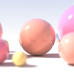
Run the program. If it is working correctly, you should see a single sphere
that appears as a disk or circle.
Now modify the traceIndividualRay method so that it returns the color of the
Surface with the closest point of intersection.
Modify the buidScene function in Lab.cpp to add additional Sphere objects to
the scene. Run the program. Place some of the spheres so that you can verify
that the nearer Sphere objects cover those that are further from the view
point.
Planes
Complete the findClosestIntersection method of the Plane class. Use the
Chapter Four notes as well as the Sphere findClosestIntersection method as a
guide.
Modify the buidScene function so that a horizontal plane is added to the
scene. Run the program. Make sure it works. Add additional planes if you
desire.
If you have a plane and a few spheres, your scene might look something like
the following.
Turn it in
- Copy the folder containing your solution to the desktop.
- Change the name of the folder to CSE287LabFour followed by your unique identifier. For instance “CSE287LabFourBachmaer.”
- Open the solution. Make sure it still runs.
- Clean the solution by selecting Build-]Clean Solution. (The will delete all the intermediate temporary files that are part of your project and reduce the size of your submission.)
- Make sure your solution does not include a .sdf file of a ipch folder.
- Zip up the solution folder using the standard windows compression tool. (No 7zips, rars, etc.)
- Submit your zip archive of the solution through canvas.
You will need to have this project available and complete when you start the
next lab.


